Agilent 101: An Introduction to Electronic Measurement
|
|
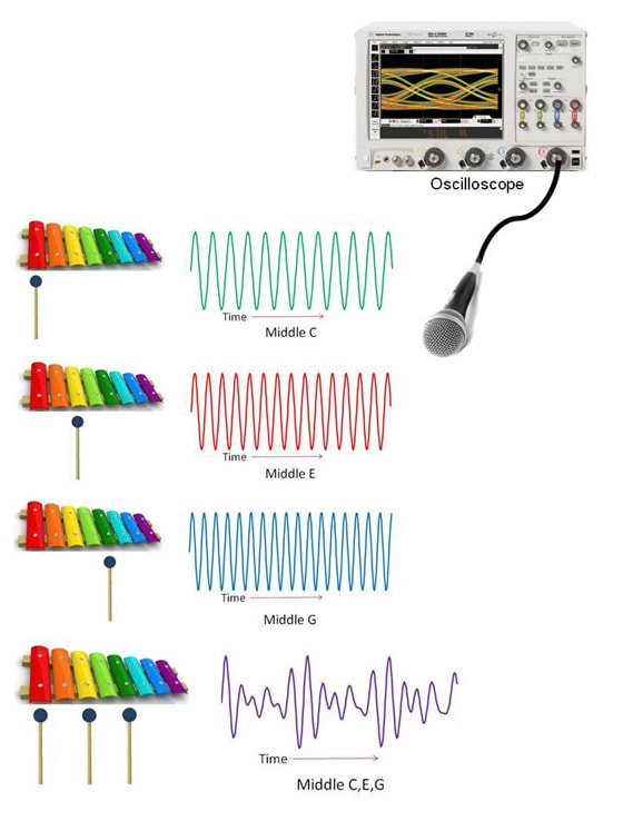
In order to explain radios, I need to talk about sound. I apologize if some of this is very elementary, but as the famous physicist Enrico Fermi once said, "Never underestimate the joy people derive from hearing something they already know." If I take a xylophone and hit it with a little hammer, I get a sound. Using a microphone connected to an oscilloscope, I can see this sound as a waveform. With a xylophone, I get a sine wave. If I hit three different notes on the xylophone, the sine waves have different frequencies. If I hit all three notes at the same time, I get a more complicated wave form. It's the sum of those three signals.
A sine wave can be defined by three parameters: the amplitude (its height), the frequency (how rapidly it cycles), and the phase (the time position of the peaks). Sine waves are the most important signals in electronics for a variety of reasons, including the fact that any waveform – no matter how complex – can be decomposed into a sum of sine waves. This phenomenon was first investigated by Joseph Fourier, so it is called the “Fourier transform.” Oscilloscopes and spectrum analyzers
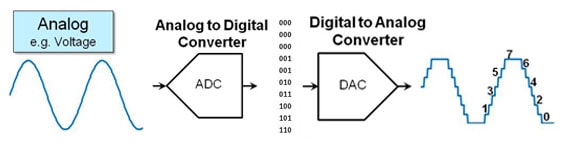
For modern instruments, if I want to measure a waveform in the analog world, I need to turn it into numbers as fast as possible. The most demanding components in an oscilloscope are associated with converting the signal into computer bits. This is done with an analog-to-digital converter, which samples the waveform at evenly spaced intervals of time. At each interval, it takes a measurement of the analog voltage and converts it into a number. There’s always a trade-off. The faster I make the measurement, the fewer bits I’m going to be able to capture accurately.
We have another class of instruments called spectrum analyzers, which analyze a signal in the frequency domain. If I play my chord on the xylophone – all three notes with the same amplitude – I will see three peaks on the spectrum analyzer. So an oscilloscope – a time-domain instrument – will show a signal as a waveform in time. A spectrum analyzer – a frequency-domain instrument – will show that same signal across a spectrum of frequencies.
AM and FM radios
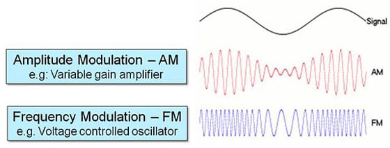
A time-honored way to communicate over distances is with some kind of wave that carries the signal. By modulating that wave, I create the communications signal. This is called a modulated carrier communication system. The ancient Romans used mirrors to reflect the sun for long-distance signaling. The same idea is behind the signal light used for communicating from ship to ship with Morse code. Here the carrier wave is visible light. By modulating the light – flashing it on and off – a sailor on one ship creates a message. An observer on another ship is able to read the message by detecting – in this case, seeing – how the carrier wave changes. One advantage of a modulated carrier is that it enables you to put many different signals on a single carrier. For example, you might use different colors of light to carry several messages at the same time. Another advantage is the ability to choose a carrier wave that can travel long distances. Such carriers include a radio wave that can cross the country through the air, an optical signal that can travel hundreds of miles in a glass fiber-optic cable, or TV signals that can travel to your home in a coaxial cable. If I want to create a carrier-based communication system, I need to have some way of changing that carrier. In the shipboard communicator, I simply turn the light on and off. In radio technology there are two popular modulation techniques, amplitude modulation and frequency modulation. These give us the familiar AM and FM dials. With amplitude modulation, I start with a carrier wave that is a radio frequency (RF) – for example, 1340 kHz. I use my audio signal to control the amplitude of the RF carrier, using a device such as a variable gain amplifier. This produces an amplitude-modulated signal. With frequency modulation, I also modify the carrier signal, except instead of varying the amplitude I vary the frequency. I could do this with a device such as a voltage-controlled oscillator.
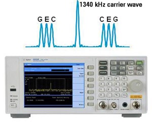
What does an AM waveform look like on a spectrum analyzer? The spectrum of our original xylophone chord had three peaks, for the C, G and E notes. However, the spectrum of the modulated signal actually has seven different tones. In the center is the 1340 kHz carrier wave. The amplitude modulation process creates three new tones at frequencies just above the carrier wave, as well as a mirror image of these tones just below the carrier wave.
Spectrum Analyzer A radio receiver has the task of reconstructing the original signal that was used to modulate the carrier wave. For amplitude modulation, this is pretty easy. You merely need to filter out unwanted noise and detect the amplitude of the signal, just like the sailor’s eye does with the ship-to-ship system. Once the signal is reconstructed, it can be amplified and played through the radio’s speaker. Advanced concepts
For example, Agilent makes frequency synthesizers that generate very accurate sine waves. And by very accurate, I mean many digits of accuracy, like 10.00000000 GHz. How do we get this degree of precision? We start by building a single fixed-frequency oscillator that is very accurate and stable. A crystal oscillator uses a quartz crystal that vibrates at a particular frequency. By controlling the temperature and environment very carefully to ensure the stability of the crystal, we can end up with a very accurate 20 MHz oscillator. From there, we can use other technologies to manipulate that 20 MHz signal. In frequency multiplication, we use nonlinear components to generate harmonics of the 20 MHz signal at even multiples of 20 MHz. For example, the 100th harmonic would be at 2 GHz. In frequency division, we can do the opposite. If we divide a 2 GHz signal by two, we get a signal at 1 GHz. In frequency mixing we multiply two signals together. If we do this for two sine waves and view the result with a spectrum analyzer, we’ll find two peaks, one at the frequency given by the sum of the original frequencies, and the other at the difference. We can apply this technique to perform frequency translation, in which a signal can be moved from one frequency to another. For instance, we can take a 1.02 GHz signal and move it to 20 MHz by mixing it with a 1 GHz sine wave. We can even translate a complex modulated carrier to a new carrier frequency, while retaining exactly the same modulation. Years ago, AM and FM were essentially the only practical ways to create a communication system. With today’s transistors and digital technologies, we now have incredibly complicated communication formats. There’s frequency shift keying (FSK), a digital version of FM. There’s amplitude shift keying (ASK), a digital version of AM. There’s phase shift keying (PSK), which modulates the third characteristic of a sine wave, the phase. We can combine these methods to achieve quadrature amplitude modulation (QAM), which modulates and sums two carrier waves that are 90 degrees out of phase with each other. I’ve only scratched the surface on how complicated these modulations can get. The point is that today’s communication protocols are extremely complex. In order to produce signals that have these complicated modulations, or to analyze them, we have to have more sophisticated electronic instruments. After converting from analog to digital, we can do all kinds of digital signal processing (DSP). In direct digital synthesis (DDS), we can digitally generate a signal by computation – including the sine wave carrier and any desired modulation – then convert the signal to analog with a data converter. Agilent can create a much more powerful spectrum analyzer or signal analyzer by doing sophisticated computation in the digital domain. Agilent also designs very complex instrument systems all in one box. The classic example is our mobile phone tester, which can generate and analyze all the different modulation formats that are used in mobile phones. This instrument can set up a call with the phone. It can measure all the parameters that you need to know if you’re manufacturing a cell phone. It can run a test of the components of the cell phones that are coming off the assembly lines. As integrated circuits become more powerful, communications engineers are designing more and more complicated communication formats to get more efficient use of the electromagnetic spectrum.
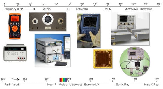
Today, Agilent spans an enormous swath of the electromagnetic spectrum. From Bill and Dave’s original audio oscillator, our first product, we now go all the way up into X-rays with the systems we’ve acquired from Varian. Agilent builds each instrument to serve a variety of test needs. Our engineers have a much harder job than the people who are building phones and radios. A customer may be building a communication system at 2.5 GHz, but Agilent has to build an instrument that works for everybody’s device, whether it’s a phone, a radio, a wireless router or a cable TV system. Agilent’s advantage is that we have very smart people who have been working on these technologies for years, whether it’s our fundamental expertise in GaAs (gallium arsenide) integrated circuits, in microwave test accessories and PC boards, in custom digital ASICs (application-specific integrated circuits), in analog-to-digital converters, in signal processing algorithms, in instrument design or in user interface software. Our experience and expertise gives us our competitive edge. And as long as we continue to innovate and push the boundaries of technology, we will continue to hold a leading position in electronic measurement.
February 2011
|