To access your Agilent account, please sign in again.
The Gas Chromatography (GC) inlet, together with the GC column and the detector, are three discrete parts of every GC system. The GC inlet is the interface through which samples are introduced into the GC column.
The GC inlet liner, a crucial component located within the body of the inlet, is responsible for sample vaporization. Understanding the role of inlet liners in GC systems is key to appreciating their significance. The frequently asked questions about GC inlet liners delve into their key features, aiding in your understanding of GC liner selection and maintenance.
Located within the body of the inlet, the GC liner’s primary role is to vaporize the sample and introduce it onto the column while safeguarding the sample from degradation and contamination. Inlet liners come in various liner types to accommodate different sample types and method conditions, underscoring their crucial role in maintaining sample integrity.
Agilent provides a diverse range of GC liners for different inlet types, each designed for specific modes of injection. These different types of liners include Splitless Injection Liners, Split Injection Liners, Ultra Inert Deactivated Liners, and more. Agilent’s Inlet Liner Selection Guide and GC Inlet Liner Selection Tool are valuable resources for selecting the most suitable liner based on your analytical requirements.
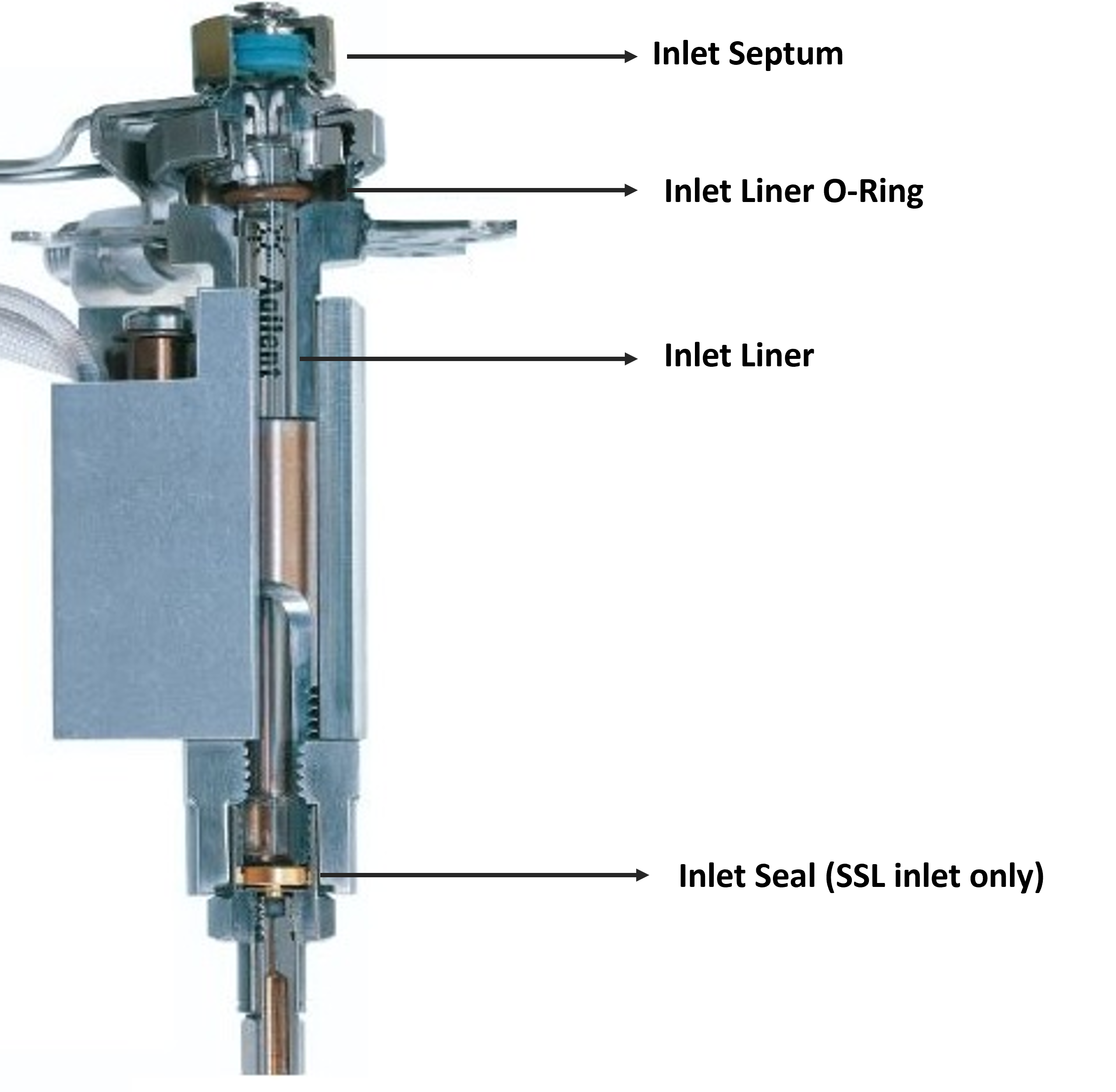
Several essential consumables work in tandem with the GC inlet liner during sample vaporization. These consumables, including the inlet septum, liner O-ring, and inlet seal, play a crucial role in isolating the sample flow path and maintaining the integrity of the GC system.
Inlet Septum
These small silicone discs create a resealable barrier at the top of the injection port, preventing leaks and maintaining consistent pressure within the inlet during injections.
Septa must exhibit resilience to repeated needle piercings and be chemically inert to avoid interfering with sample analysis. Regular inspection and replacement of septa are necessary to ensure proper sealing and reliable chromatographic performance.
Inlet Liner O-Ring
Installed against the outer surface of the inlet liner, these O-rings create a seal between the inlet weldment and turn-top, isolating the sample from the flow path.
Agilent offers fluorocarbon (FKM) and graphite-based O-rings based on application requirements.
Inlet Seal
Unique to the S/SL inlet, positioned between the base of the inlet liner and the head of the column, the inlet seal ensures a leak-tight connection at the base of the inlet, preventing the loss of carrier gas and sample components as it passes through the inlet liner and onto the column.
During split mode injections, the inlet seal redirects a portion of the sample solution toward the split vent based on the selected split ratio.
1. Geometry
The geometry of the GC inlet liner includes parameters such as its length, diameter, shape, and material composition. These factors collectively influence the efficiency of sample vaporization, transfer, and injection into the chromatographic column. The geometry of the GC liner can impact the resolution, sensitivity, and reproducibility of chromatographic analysis.
Liner type is often dictated by the sample and method.
Optimizing the inlet liner geometry is crucial for achieving accurate and reliable analytical results. Adequately adjusting these parameters can help improve sample vaporization, minimize inlet discrimination, and enhance the GC’s overall performance.
2. Volume
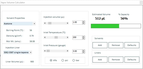
The sample composition, inlet types, inlet temperature, and pressure influence how much a sample expands following injection. The GC liner’s volume must be large enough to accommodate the gaseous sample without backflowing through the septum purge flow and split line (backflash). If the volume is too large, the sample may not efficiently transfer onto the column, leading to peak tailing, poor peak-area reproducibility, and carryover.
Agilent's Vapor Volume Calculator can help determine sample expansion and aid GC liner selection.
3. Packing Material
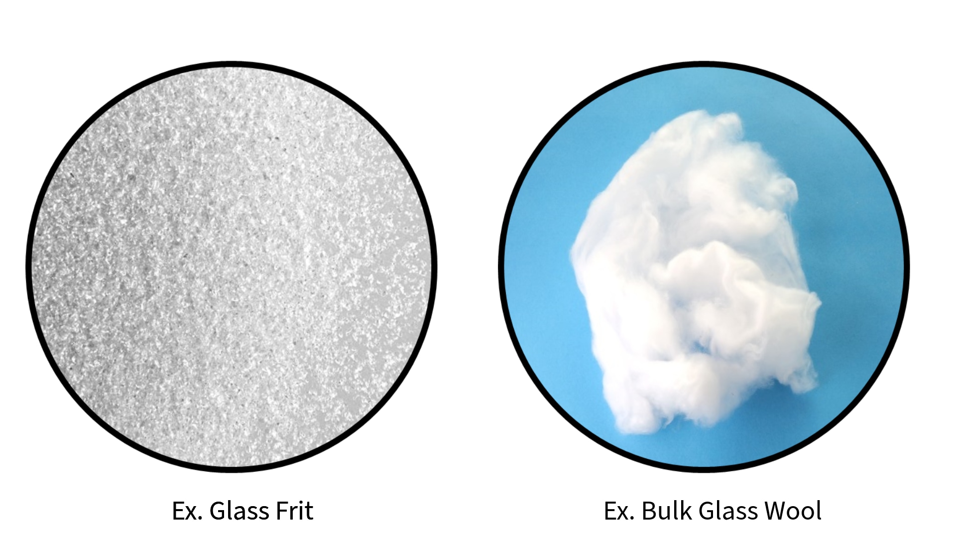
Glass wool is a popular feature in many GC inlet liner configurations. Often used in conjunction with complex sample matrices, the wool enhances the vaporization of heavier analytes due to its large surface area and high heat capacity. The barrier creates turbulence within the flow path, mixing the sample with the carrier gas and preventing liquid samples or non-volatiles from contacting the head of the column or inlet seal.
The volume and location of the wool can also influence analytical outcomes. Wool positioned towards the base of the GC liner is often favorable for injections with lower split ratios, wherein the sample may be expected to reside within the inlet for an extended period. This allows ample room for gradual solvent vapor expansion while focusing volatile solute towards the head of the column.
Wool positioned towards the middle or top of the GC liner is more common with higher split ratios where sample residence times are expected to be comparatively shorter, and rapid volatilization is necessary. Positioned high enough, the wool will contact the tip of the needle during injection, ensuring the entire sample is transferred and reducing the potential for carry-over to the next injection.
In addition to wool-packed GC liners, Agilent also offers low (5190-5112) and mid (5190-5105) frit liners, in which a porous glass frit replaces the glass wool and is sintered to the wall of the liner. The more homogeneous pore structure allows even heating of the sample and improved retention of non-volatile matrix elements. An internal comparative study demonstrated 3X greater longevity compared to the wool-packed equivalent.
4. Composition
Agilent’s inlet liners are primarily manufactured with high-quality, borosilicate 3.3 glass. Preferred for its low coefficient of expansion, laboratory-grade borosilicate glass can withstand the high temperatures imposed by the inlet and is resistant to thermal shock. The high silica content (≈ 80% SiO2) infers greater resistance to alkalis, acids, and volatile organic substances. Additional inert coatings can further reduce the reactivity of silanol groups (Si-O-H), prevent the accumulation of active residues, and minimize discrimination.
Agilent’s non-deactivated quartz glass (≈ 95% SiO2) inlet liners are recommended for transferring pre-volatile and gaseous samples through a preheated inlet and directly onto the column. Even the most robust deactivation processes are susceptible to eventual degradation with prolonged exposure to harsh inlet conditions. The high-purity fused silica glass offers exceptional longevity when injecting relatively clean, gaseous samples. These GC liners are typically used with GC Headspace, Thermal Desorption, or Purge and Trap applications.
5. Surface Deactivation
Untreated, borosilicate glass can contain numerous exposed silanol groups. To prevent unwanted secondary interactions and extend the effective lifetime of the GC liner, these groups can be chemically derivatized via a surface deactivation process, reducing the number of active sites. In addition to standard untreated GC liners, Agilent offers two levels of deactivation: a standard, liquid-based DMDCS treatment and an advanced, vapor-based coating (Ultra Inert).
Agilent's superior Ultra Inert (UI) coating is highly robust and resistant to degradation due to hydrolysis within the heated inlet. Its use ensures the complete transfer of analytes and is highly recommended for trace and complex forms of analysis.
The dominant injection mode for capillary gas chromatography, split injection mode, is typically preferred for matrix-laden samples with a high analyte concentration. The higher carrier gas flow rates associated with the technique contribute to a comparatively shorter sample residence time within the inlet, leaving high boilers susceptible to potential discrimination.
Agilent offers several type of inlet liner configurations optimized for split-mode injection.
5190-2294; Ultra Inert, Straight, 990 µL, Glass Wool Inlet Liner
5190-5105; Ultra Inert, Single Taper, 870 µL, Mid-Frit Inlet Liner
5190-2295; Ultra Inert, Single Taper, 870 µL, Low-Pressure Drop, Glass Wool Inlet Liner
Splitless injection mode is often utilized for the trace analysis of samples with low analyte concentrations. With a reduced overall flow rate, analytes may reside within the inlet longer. Volatilization and recovery of high boilers may be improved at the expense of more active analytes prone to adsorption or degradation.
Agilent often recommends the following inlet liners for splitless injection mode.
5190-2292; Ultra Inert, Single Taper, 990 µL Inlet Liner
5190-2293; Ultra Inert, Single Taper, 900 µL, Glass Wool Inlet Liner
5190-3983; Ultra Inert, Double Taper, 800 µL Inlet Liner
5190-5112; Ultra Inert, Single Taper, 870 µL, Low-Frit Inlet Liner
5190-7011; Ultra Inert, Direct Connect, Double Taper, 575 µL Inlet Liner
For even experienced operators, injecting samples into the inlet by hand poses several challenges that can affect the accuracy and reproducibility of analyses, including inconsistent injection volumes, needle discrimination, and reduced injection accuracy and precision. Proper GC inlet liner selection can help to partially mitigate these risks.
18740-60840; Jennings Cup, Single Taper, 800 µL, Glass Wool Inlet Liner
Agilent’s Multimode (MMI) enables the preconcentration of trace-level, thermally labile compounds prior to introduction onto the column. In solvent vent mode, the inlet is kept at a low initial temperature as the liquid sample is introduced and deposited on the wall of the liner. As the inlet temperature increases, the evaporated solvent is vented off ahead of the analyte of interest. After a brief holding period, the inlet switches to splitless mode for analyte transfer to the column. Agilent often recommends using a 2mm, dimpled inlet liner for these types of injections.
5190-2297; Dimpled, Single Taper, 200 µL, Inlet Liner
Certain GC techniques involve introducing a sample directly into the inlet in an already gaseous state, including analysis by: direct injection, headspace, purge-and-trap, on-line sampling, and thermal desorption. In these scenarios, the inlet liner’s primary purpose is to facilitate the quick, efficient transfer of the volatile sample onto the column. Agilent often recommends a straight, narrow-diameter liner (1-2mm) for this. The small internal diameter results in higher linear velocities of the carrier gas as it passes through the inlet, preventing excessive diffusion and broadening peak shape.
Product Recommendations -
5190-4047; Ultra Inert, Straight, 60 µL (1mm ID), Inlet Liner
5190-6168; Ultra Inert, Straight, 250 µL (2mm ID), Inlet Liner
For use with the XLSI Transfer Line Interface Accessory, Agilent recommends the 2mm option to ensure proper fitment.
A brief step-by-step overview –
A. Turn off the inlet heating zone and set the oven temperature to 35°C. When the oven has reached the set point, and the inlet is at a comfortable temperature to touch, turn off the GC oven temperature, inlet temperature, and inlet gas supply.
B. Using the inlet nut spanner, remove the inlet nut and gently lift the nut up and off the inlet liner. Take care not to chip the top of the liner or bend the 1/16" gas line tubing connected to the inlet weldment.
C. Using tweezers, gently separate the O-ring from the metal inlet surface, then carefully lift the inlet liner straight up.
D. Inspect the weldment surface, removing any residue from the sealing surface, and wipe the exposed surface with clean, GC-grade solvent.
E. Look into the inlet and inspect the gold seal. If the gold seal is discolored and chromatographic anomalies have been observed, replace the gold seal.
F. If not pre-installed, slide a new O-ring 1.5 to 2mm down onto the replacement liner. The Agilent logo and Spark symbol are inserted face first and face the bottom of the inlet unless otherwise indicated by the liner print.
G. Install the replacement liner and then retighten the inlet nut. Liners should be installed so that the Agilent Spark logo and Agilent name (starting with the 'A') are inserted first and are closer to the bottom of the inlet. The only exception would be a liner with the flow direction printed on the liner body itself.
H. Turn on the inlet gas supply and allow the inlet and column to purge with carrier gas for 10 to 15 minutes.
I. Turn on the inlet heating zone, set the oven temperature to the highest ramp temperature in your method, and hold for another 10 to 15 minutes. If subsequent runs show contamination, you may need to bake out the inlet further.
GC Intelligence, found in the Intuvo, 8890, and 8860 GC Systems, offers self-guided maintenance procedures with step-by-step instructions on everyday maintenance tasks. Built-in help and information are accessible by the instrument touchscreen or browser interface.
O-rings form a gas-tight seal between the inlet weldment and turn-top, isolating the sample flow path. Agilent offers fluorocarbon (FKM) and graphite-based O-rings based on application requirements.
Fluorocarbon-based O-rings are generally preferred for most GC and GC/MS applications with a peak inlet temperature below 350°C. To avoid contamination from surface-level impurities, fluorocarbon O-rings should be conditioned prior to use. Agilent O-rings are preconditioned, certified, and shipped ready for use. Agilent FKM O-rings feature a unique plasma treatment to create a low-friction, non-stick surface without impacting elasticity. This process ensures the O-ring retains its integrity through multiple temperature cycles and is easily removed during maintenance.
For higher-temperature applications up to 450°C, Agilent recommends using high-purity graphite O-rings. The soft, malleable material conforms to the shape of the sealing interface and is highly resistant to thermal expansion or contraction, ensuring an efficient seal over numerous temperature cycles. A notable caveat is graphite’s inherent porosity, which can be problematic for oxygen-sensitive techniques such as analysis by ECD or MSD.
O-rings are non-reusable and should be changed alongside the liner during preventative maintenance. Follow OEM guidelines for inlet liner installation. Overtightening the inlet can cause the O-ring to extrude, potentially compromising performance.
Agilent Ultra Inert (UI) Liners feature a pre-installed fluorocarbon O-ring for ease of use and installation.
Over time, inlet liners may become prone to contamination either due to the accumulation of non-volatile residues or progressive polar/polar interactions between the surface of the liner and the analyte, resulting in discrimination. Inlet discrimination can be characterized in a few ways: by reduced peak response, broadening and tailing, and the introduction of unwanted 'ghost peaks.' However, how frequently a liner must be exchanged is highly dependent on the method, sample composition, and throughput. Agilent recommends evaluating the liner at least once weekly to determine if there are any issues.
Ex. Excessive build-up of non-volatile residues within an inlet liner.
On Agilent smart GCs, liner performance may be evaluated through systemic GC Performance Evaluations. Blank Evaluation monitors the chromatograph to ensure there are no extraneous peaks or baseline anomalies. Peak Evaluation, available on the 8890 and Intuvo GCs, monitors up to 10 peaks in the chromatogram for key attributes such as area, height, symmetry, resolution, and retention time. This feature can be configured in the browser interface or the chromatography data system.
Early Maintenance Feedback (EMF) is another helpful feature of Agilent GC systems and software that allows users to monitor the maintenance requirements of their GC proactively. Using preset injection- and time-based counters for various consumables and maintenance parts, users can receive a reminder when maintenance is due on their instrument before potential degradation impacts chromatographic results.
Inlet liners are a consumable product. Repacking inlet liners is not advised and is strongly discouraged. As many experienced chemists will attest, effectively packing an inlet liner is as much an art as a science. Minor voids within the packing material can modulate the sample flow path, potentially impacting sample volatilization and analyte recovery. Any scratches or micro-abrasions incurred during the process can host active sites and diminish the performance of any surface coatings or treatments. Glass wool is also exceptionally delicate and prone to fracture, creating a source of unwanted debris within the inlet.
The cost to re-run samples and time spent troubleshooting poor performance often exceeds any savings otherwise achieved through re-conditioning.
This online selection tool simplifies the often complex task of inlet liner selection for GC analysis allowing users to compare different liner types liner side by side, including compatibility with various intel types, injection techniques, and GC instruments.
The Vapor Volume Calculator determines the expansion volume of a GC sample solvent at a given inlet temperature and pressure for a specific GC liner. Performing this calculation ensures that the GC liner is not overloaded, which can cause backflash.
The Agilent Community provides easy access to information produced in collaboration with Agilent experts worldwide. Learn about best practices to maintain and troubleshoot your GC with different inlet types.